So you have no fabrication experience, average mechanical skills, basic hand tools, lots of time, and you want to turbo you’re LS1? Well then you’re in the right place :D This write up will follow along with the building of a single front mount truck manifold turbo kit on Chris’s (Sideway240sx) 1998 Trans Am. Going into this we had NO welding skills, NO fabrication skills, and NO idea what we were getting into. I must say though that we made it through with very few problems. I am going to try and keep this article as technical as possible, and only give details on areas that we felt were not addressed anywhere else.
Were going to start with what parts you will need to get this project going. Below is a list of everything that you need to make a truck manifold turbo kit. The parts listed in prentices are the parts we used on our build. This is obviously not an end all be all list because everyone has different goals for their cars. Also I suggest having everything that is bold in you’re possession before starting work, it will make you’re life much easier.
Truck Manifolds (2003 Silverado 1500 6.0 with no EGR)
Turbo (PTE GT42-76 with a 1.12 A/R)
Waste gate (Tial 44mm)
Blow off valve (Tial 50mm)
Intercooler (Garrett core 31”x12”x 3” with 3” inlet/outlet)
Turbo flange (T4)
3 bolt manifold flanges
Piping (2.5” for crossover, 3” for IC, 4” for DP/Exhaust)
Fittings and line for oil feed (M10x1.25 to -4 AN and 6’ of -4 line)
Fittings and line for oil drain (M14x1.5 to -10 AN and 3’ or -10 line)
Bolts for turbo
Bolts for manifolds (M10x1.5 35mm Long)
Vacuum hose
Alternator relocation bracket (Smokinhawk)
Belt
Permetex (Copper)
T4 Turbo gasket
Silicone couplers (MAF is 3.5” and the TB is 4” so you will need transitions)
T-Bolt clamps
Injectors (60 Lb/Hr Siemens)
Fuel Pump (Walbro 255 Lt/Hr)
O2 Bungs (2 for narrow band, and 1 for wideband if you want)
OPTINAL:
Power steering lines
Summit PN: (more information can be found in the Truck Manifold FAQ)
EAR-991955ERL (2 are required)
EAR-991956ERL
RUS-620421 (3 are required)
RUS-620401
RUS-670300
RUS-632610 (6 foot section of power steering hose)
Radiator (Griffin 27.5” x 15.5” x 3”)
Aftermarket fans (Dual 10” Proform 1000 CFM)
Oil dipstick (Lokar braided)
Threaded IAT sensor (Factory replacement for Typhon/Syclone and bung is 3/8 NPT)
O2 sensors (Corvette rear’s)
As far as materials are concerned, that is completely up to you. We used mild for just about everything, because of cost and our ability to weld it ourselves. For the piping we used all 16 gauge, and just ordered a nice selection of bends in each size listed, and a few feet of straight. The bolts listed above are the size that we needed to replace the factory studs. I am not going to say that they will work on every manifold out there, but for us we were able to unscrew the studs and use a bolt instead. Lastly the oil feed, and drain sizes very to each turbo, so check to see what yours requires before you order parts.
Ok, let’s talk turkey, er’ um tools. Other than you’re basic hand tools, all you need is a 4 ½ angle grinder and a welder. Now you don’t have to go out and buy a welder, you can always have it welded by someone else or find a friend with one. We chose to just spend the money a buy a small MIG welder (Hobart handler 140) because we had other uses for it. The angle grinder is another not necessary tool, but is basically worth its weight in gold. If you decide to spend the cash and buy you’re own welder, it’s almost a must have for metal prep and so on. The main use of the angle grinder is for cutting the pipe, so if you have another way, and you’re not doing you’re own welding, you don’t really need one. I can tell you we tried a 9” band saw for cutting the tubing, and it just plain did not work. We tried a couple of different blades, and messed with it for hours, all it did was frustrate us. The angle grinder worked perfect every time, but it takes a little more patience and a steady hand.
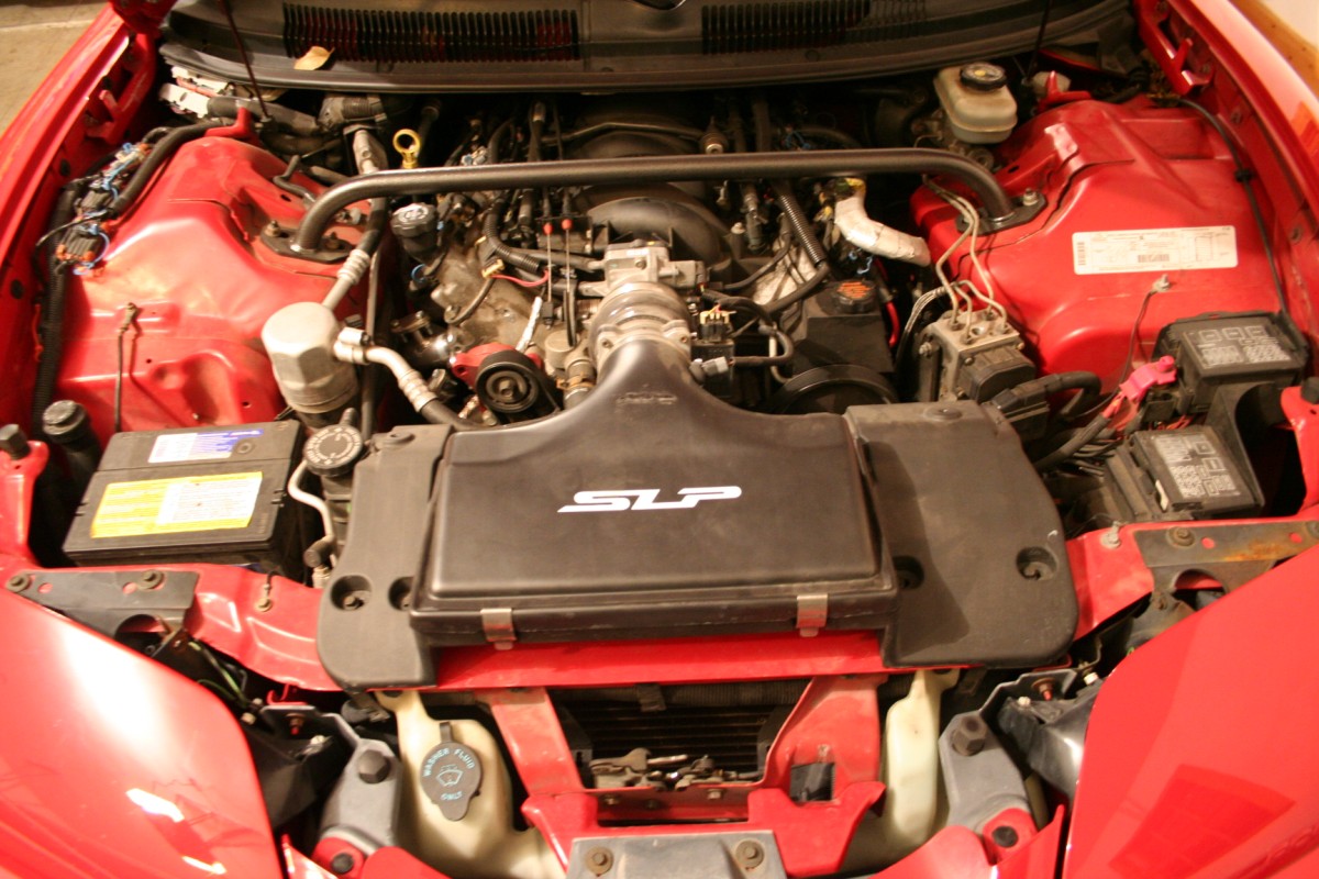
Now that you have all your parts and all your tools, let’s get to work!! First things first open your hood, and see this (or something similar)
Now all you have to do is rip all that out, well almost all of it. Start from the top and work your way down is the best advice here. Here is a list of what needs to come off, maybe more if you’re getting a little more hardcore.
Lid (including the IAT sensor, and MAF)
Lower air box
Radiator, fans, and hoses
AC (Yes, you will have to ditch the AC, but that’s just extra weight anyway)
Manifolds (or headers)
Exhaust
Alternator (will need to be relocated)
Bumper and support
The only real problem we had during this part was the front bumper.
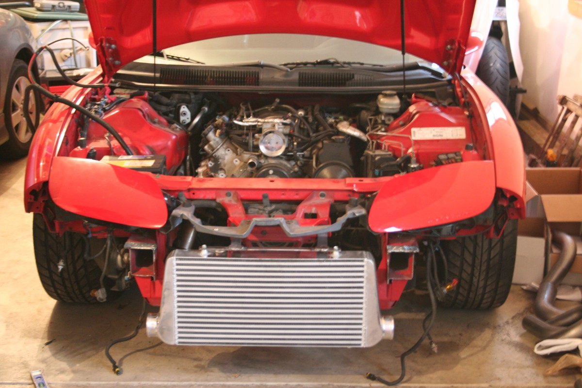
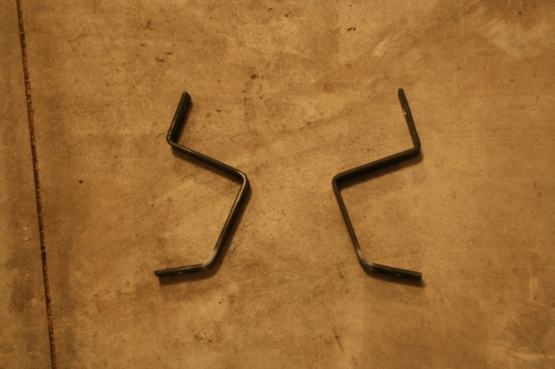
Finally its time to start cuttin’ and weldin’ YAY!!! We started with mounting the intercooler, no real reason for starting there, just wanted to see it on the car. As with everything else there are a few ways to mount the intercooler, we chose the custom mount way. I have seen people cut the factory bumper support and used that for the upper support, we didn’t do that but that’s one option as well (and honestly it looks the easiest). What we thought was the easiest (probably the second easiest in reality) was to take a piece of flat stock (1”x1/4”) and run it across the top of the intercooler between the two bolt holes. Then it’s just a matter of drilling some holes for bolts to go through. I’m not to sure how to explain the next part but Ill try. If you look at the latch from the front you will see two bolts on either side that hold the latch to the center support (the piece between the latch and the lower radiator support). Basically what I did was take two pieces of flat stock, drilled them in the same place toward the end, and bent them 90° in the same place (centering the holes I drilled between the end and the bend, that was maybe 1 ½ inches). Then I bolted them to the car and hung the intercooler off of them, with the piece that is bolted between the two top mounts. I only did this to mark where I needed to cut the tow pieces coming off of the car, and where to weld them to the crossbar. Make sure to center the intercooler, AND make sure that its not crooked front to back. After that it’s just a matter of a little welding and, wahlah, upper intercooler bracket. If that was confusing, just look at the pictures that should help.
Lower Ic Bracket
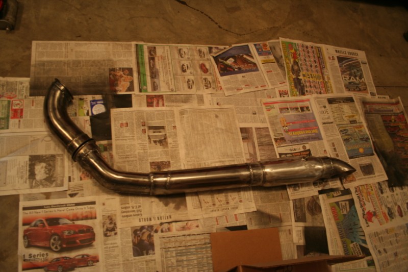
Then we started right in with making our merge, figuring that was going to be the hardest thing to make. It depends on where you want to place your turbo, or if you’re going to do a twin setup how you need to make your merge. On ours we put the turbo in the semi standard location of in front of the crank pulley. If that’s the route you are going to go, then follow along. I started with cutting two of the 2.5” 90°’s. Cut them down as short as possible, while still leaving enough room for the waste gate. You want the two sides to completely merge before the waste gate for the best performance. Probably the hardest part of making the merge is cutting the bends evenly. I did this by eyeballing it more or less, although a little measurement wouldn’t have hurt. My thinking with how I did the cutting was that if I cut both of the pipes right in the middle then I would end up with one 2.5” pipe. That wouldn’t work because I already knew that the T4 flange was substantially bigger than one pipe. So what I did was lay one bend on the flange with the edge touching the side (see drawing) and marked the pipe at the middle of the flange (which I measured and marked first) Then I took the other bend on the opposite side, and did the same thing, and tried to cut them as straight as possible.
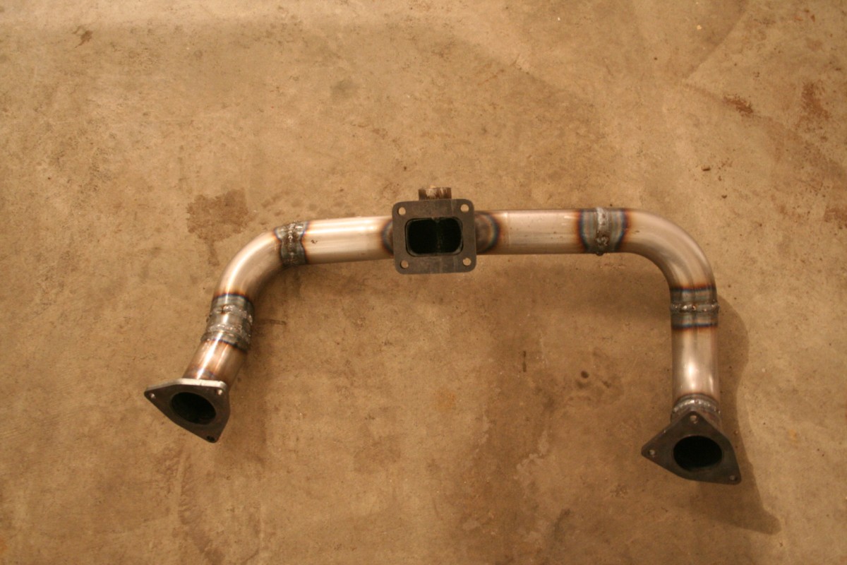
That method worked pretty well, but my cuts were not the best leaving me with some gaps to fill while welding. After you get the pipes cut, tack them together and put them on the flange, they should be close to working. Now it’s just a matter of doing some heatin’ and beatin’. I narrowed the two in a vice first so that they would fit in the merge, then worked on the narrow sides, and finally corners. I made ours fit in the flange, but it isn’t necessary. All that’s left now is to weld it all up.
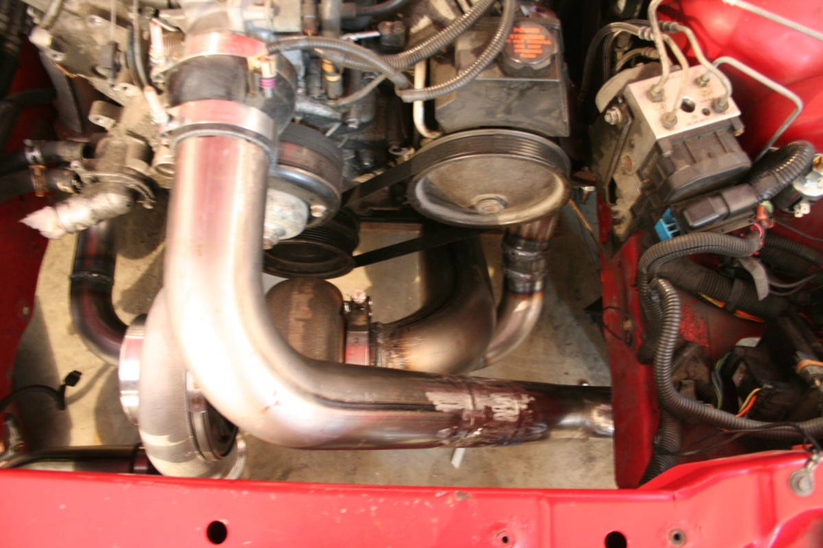
The next step is to figure out turbo placement, that part is a little tricky. We noticed in our research that most people face the exhaust toward the passenger side, most of those people were also using a Turbonetic’s TC76 (MUCH smaller than the turbo we chose, which also is our reasoning for a vertical radiator). We tried that, and it simply did not work for us. Like I said earlier though, every setup is different, and if you can get away with it point the exhaust exit toward the passenger side. There is enough space to fit a 3” pipe through the mount (between the mount, K-member, and motor) there is NO space on the driver side for anything. There is a lot to take into consideration with placement, more than exhaust routing. Some of your main concerns are exhaust routing, IC piping (we had an issue with the outlet of the turbo being directly on the crossover pipe, luckily we checked first), radiator placement, fans, belt, and so on. Try to picture EVERYTHING back together, and think if anything will be in the way of anything else. This is also the time to make the decscsion on changing to pusher fans, and or a vertical radiator. Last thing to really pay attention to here is the drain, remember that it’s a gravity drain so it will need to have a downward slope. Make sure the turbo is high enough to gravity drain, and figure out where you are going with your drain.(timing cover, or the oil pan, and where on the oil pan) One last little thing we did, was run electrical tape around all the pullies just to kind of give us an idea of where the belt will be.
Once you get your placement all figured out, it’s just a matter of getting the manifolds to the merge. We had already welded a few inch’s of straight pipe onto our flanges before we started, so we just bolted those on. We had the merge sitting on some blocks in the location we wanted and just started eyeballing some bends. We started on the driver side, but it doesn’t really matter what side you start on. Just work your way from the manifold flange to the 90 coming out of the merge. One side usually has a little kink bend in it from what we noticed. Ours happened to be on the driver side, but most others that we saw were on the passenger side (Again that was on cars with the TC76 and the exhaust facing the passenger side). The best thing to do is to tack it all before you just go and weld it all solid, just incase you need to tweak it a little.
After both sides are all welded up you get to put the turbo ON the car :D Your first big milestone, aren’t you so excited (we were). Ok, excitement (and picture op) over, back to work. We moved on to running the intercooler piping, which is more of the same really. Like I have already said a few times here, make sure to take EVERYTHING into consideration when you are figuring out routing. Because of how we had to face the turbo, we went hot to the passenger side, and cold pipes on the driver. For us the hot pipes were about as easy as it gets, just two 90’s. The cold side was a little more complex, but still not bad. Every car is different, and everyone has different preferences for how they want it to look, so Ill leave it at that. Things to keep in mind, the MAF needs to be as close to the throttle body as possible, the blow off valve needs to be before the MAF, and depending on how you want to do your IAT sensor you will either need a hole or a bung welded in. We also ground the welds on the intercooler piping smooth, no reason for this other than looks. The only risk to doing that is more of a possibility of pinhole leaks if your welds aren’t good.
On to the down pipe now, this is just more of the same. Since we know every set up will be a little different, it’s hard to say what to do here. If you are able to, the best choice is to run it on the passenger side. We had to go to the hard/impossible side, the driver side. So our “down pipe” is really just a 4” 90 bend that is cut real short on one side (that was to make it fit between the crossover pipe and the motor). We opted to V-band the end of our down pipe so that we could easily remove the exhaust at the track, or when working on anything. We also put an O2 bung at the end of our down pipe (about 6-8 inches away from the turbo is the general rule of thumb) for a wide band O2 sensor. Id love to tell you how to make an exhaust, but we never got around to that. We had issues with having to go under the stock K-Member on the car because we had the exhaust on the driver side. I actually made up an exhaust that was complicated as hell. It basically changed from a 4” round into a 2.5” oval pipe (I took a 2.5” 45 bend and split it down the motor and welded in a 2” strip of metal to make the oval) then after we got past the K-Member it goes back to 4” round. It fit as good as it could, and looked pretty good, but was still to low (the car is lowered on 1.5” drop springs) so it had to come off.
Lastly i would like to touch on a couple things that will need to be addressed. first off, you will need to work on your pcv system. Look up how might mouse did his, seems to work great, and i will be doing it soon. Next even at 5-6 psi, i was floating my valve springs. Upgrading them for a turbo car is pretty much a must. I went with ls6 springs because they were free, and they should be good enough. This was also the perfect oppertunity to do pushrods.
There seems to be lots of confusion on runnign vacuum lines. What we did, and it works great is use the fitting in the turbo(not all turbo's have it) to the manual boost controller, to the wastegate. For the bov i got vacuum from the map sensor, used a t, and also went inside the car for the boost gauge.
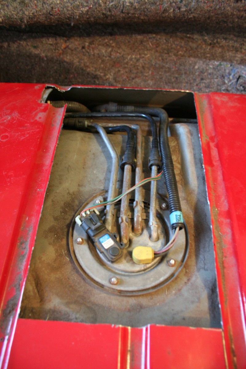
Fuel is a must for a turbo car. I used a walbro 255 and siemens flow matched 60's. To install the pump i cut up the car. See below.
For a tune, i sent out my pcm to texas speed. they got the car driveable with the 60 pound injectors but i would not suggest really getting on it untill you get it tuned properly. I also highly suggest a wideband 02 so you can tell how rich, or lean you are. For the wideband 02 bung if you are mainly a street car and running on pump gas 6-8 inches away from turbo in dp is ideal. If its a race gas higher hp car you might want it more like 10-12 inches back so it doesn't burn up.